
10.3 Faulting
A body of rock that is brittle—either because it is cold or because of its composition, or both— is likely to break rather than fold when subjected to stress, and the result is fracturing or faulting.
Fracturing
Fracturing is common in rocks near the surface, either in volcanic rocks that have shrunk on cooling (Figure 10.1.3a), or in other rocks that have been exposed by erosion and have expanded (Figure 10.3.1). Fractures, by definition, do not displace rock. There is no movement on a fracture plane.
Faulting
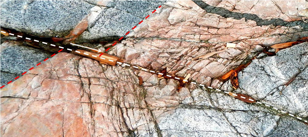
A fault is a boundary between two bodies of rock along which there has been relative motion (Figure 10.1.3d). You may recall from lecture that an earthquake involves the sliding of one body of rock past another. Earthquakes don’t necessarily happen on existing faults, but once an earthquake takes place a fault will exist in the rock at that location. Some large faults, like the San Andreas Fault in California or the Tintina Fault, which extends from northern B.C. through central Yukon and into Alaska, show evidence of hundreds of kilometres of motion, while others show less than a millimetre. In order to estimate the amount of motion on a fault, we need to find some geological feature that shows up on both sides and has been offset (Figure 10.3.2).
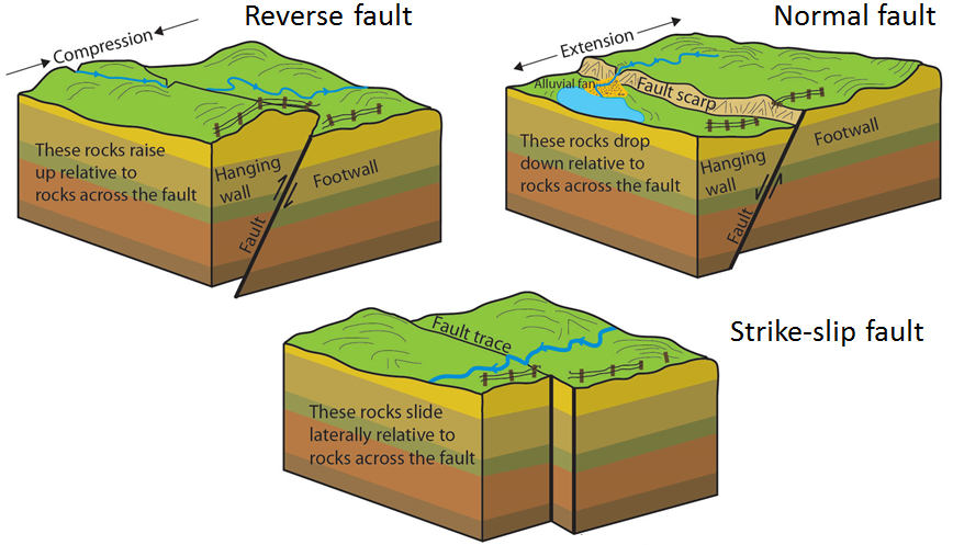
There are several kinds of faults, as illustrated on Figure 10.3.3, and they develop under different stress conditions. The terms hanging wall and footwall in the diagrams apply to situations where the fault is not vertical. The body of rock above the fault is called the hanging wall, and the body of rock below it is called the footwall. If the fault develops in a situation of compression, then it will be a reverse fault because the compression causes the hanging wall to be pushed up relative to the footwall. If the fault develops in a situation of extension, then it will be a normal fault, because the extension allows the hanging wall to slide down relative to the footwall in response to gravity. The map symbols for these types of faults are illustrated in Figure 10.3.4.
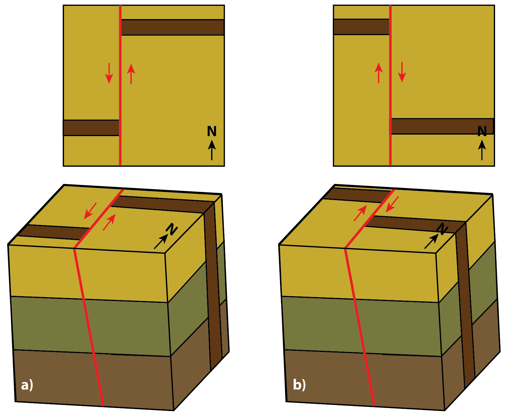
The third situation is where the bodies of rock are sliding sideways with respect to each other, as is the case along a transform fault (see Lab 1). This is known as a strike-slip fault because the displacement is along the “strike” or the length of the fault. On strike-slip faults the motion is typically only horizontal, or with a very small vertical component, and as discussed above the sense of motion can be right lateral (the far side moves to the right), as in Figure 10.3.2, or it can be left lateral (the far side moves to the left). Map symbols for these strike-slip faults are illustrated in Figure 10.3.5. Transform faults are strike-slip faults.

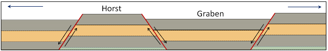
In areas that are characterized by extensional tectonics, it is not uncommon for a part of the upper crust to subside with respect to neighbouring parts. This is typical along areas of continental rifting, such as the Great Rift Valley of East Africa or in parts of Iceland, but it is also seen elsewhere. In such situations a down-dropped block is known as a graben(German for ditch), while an adjacent block that doesn’t subside is called a horst (German for heap) (Figure 10.3.6). There are many horsts and grabens in the Basin and Range area of the western United States, especially in Nevada.
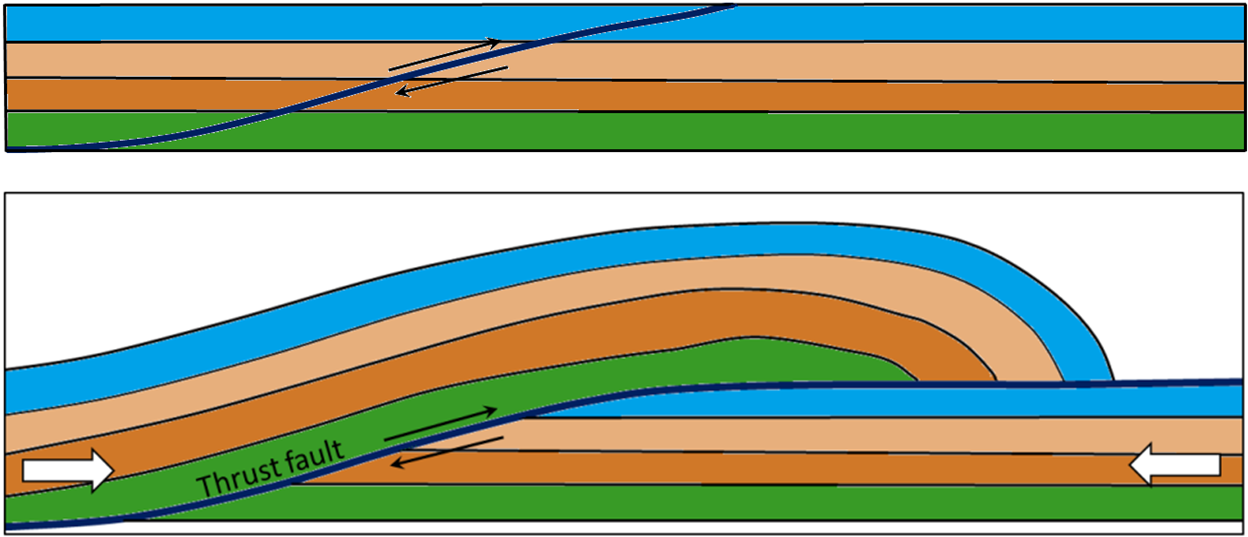
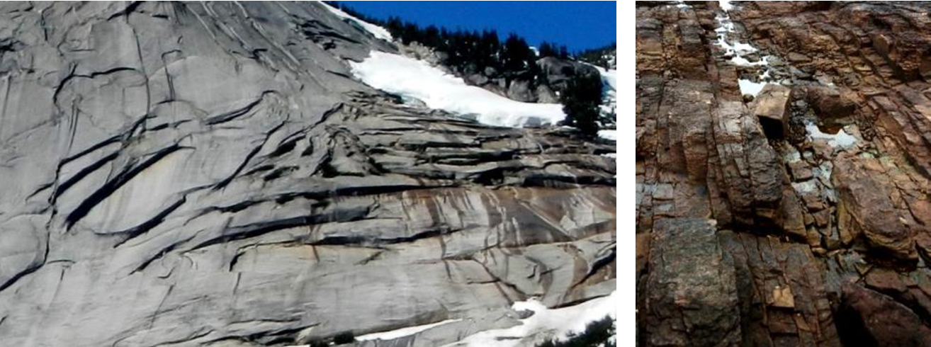
A special type of reverse fault, with a very low-angle fault plane, is known as a thrust fault. Thrust faults are relatively common in areas where fold-belt mountains have been created during continent-continent collision. Some represent tens of kilometres of thrusting, where thick sheets of sedimentary rock have been pushed up and over top of other rock (Figure 10.3.7).
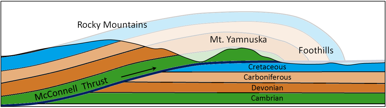
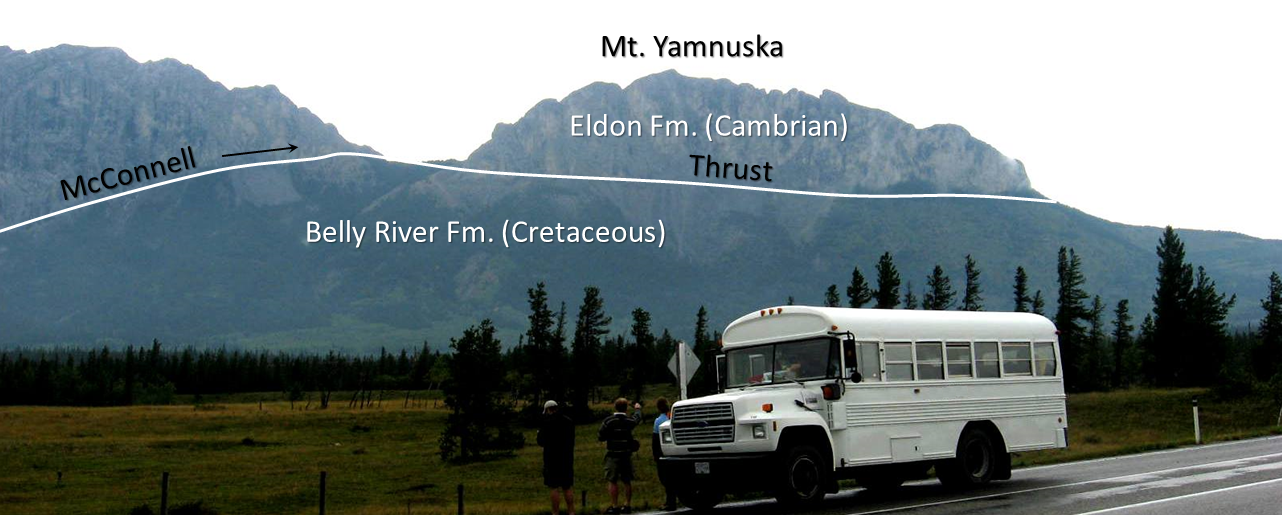
There are numerous thrust faults in the Rocky Mountains, and a well-known example is the McConnell Thrust, along which a sequence of sedimentary rocks about 800 metres thick has been pushed for about 40 kilometres from west to east (Figure 10.3.8). The thrusted rocks range in age from Cambrian to Cretaceous, so in the area around Mt. Yamnuska Cambrian-aged rock (around 500 Ma) has been thrust over, and now lies on top of Cretaceous-aged rock (around 75 Ma) (Figure 10.3.9).
Practice Exercise 10.2 Types of faults

The four images are faults that formed in different tectonic settings. Identifying the type of fault allows us to determine if the body of rock was under compression or extension at the time of faulting. Complete the table below the images, identifying the types of faults (normal or reversed) and whether each one formed under compressional or tensional stress.
| Type of Fault and Type of Stress |
| Top left (looking at a cliff face): |
| Bottom left (looking at a cliff face): |
| Top right (looking at a cliff face): |
| Bottom right (looking down onto the ground): |
See Appendix 2 for Practice Exercise 10.2 answers.
Media Attributions
- Figure 10.3.1, 10.3.2, 10.3.6, 10.3.7, 10.3.8, 10.3.9: © Steven Earle. CC BY.
- Figure 10.3.3: “Fault Types” by the National Park Service. Adapted by Steven Earle. Public domain.
- Figure 10.3.4, 10.3.5: © Siobhan McGoldrick. CC BY.
- Figure 10.3.10 (all except bottom left): © Steven Earle. CC BY.
- Figure 10.3.10 (Bottom left): “Moab fault with vehicles for scale” © Andrew Wilson. CC BY-SA.
the upper surface of a non-vertical fault
the lower surface of a non-vertical fault
a non-vertical fault along which the hanging wall (upper surface) has moved up relative to the footwall
a non-vertical fault along which the hanging wall (upper surface) has moved down relative to the footwall
a fault that is characterized by motion that is close to horizontal and parallel to the strike direction of the fault
a down-dropped fault block, bounded on either side by normal faults
an uplifted fault block, bounded on either side by normal faults
a low angle reverse fault
