
C. Primary Structures
Most of structural geology deals with structures that developed in rocks when they were deformed by tectonic processes. However, in describing structures, it’s common to find structures that were developed while the rocks were forming. These are called primary structures. It’s important to understand these structures for many reasons. They can give you information about the environment of formation of the rocks, and they can sometimes help with the analysis of later deformation.
In sedimentary rocks, primary structures are all-important clues to the environment of formation. The study of sedimentary structures is a main focus of courses in sedimentology. Here we will make a survey the most important sedimentary structures with an emphasis on the ones most useful to structural geologists. Sometimes these structures give information on things like whether the rocks have been turned upside down since their formation, so it’s important for structural geologists, stratigraphers, and paleontologists to recognize and understand them.
In igneous rocks, primary structures are also important: they can tell you whether an igneous body is intrusive or extrusive, for example.
Both sedimentary and extrusive igneous rocks are often stratified: they are organized in layers (strata) that were originally horizontal. By measuring their orientation and order of formation, structural geologists gather information about Earth history. When strata are thick they show up on geologic maps as distinct units, called formations, groups, members etc. The study of the organisation of strata is stratigraphy.
Strata and Stratigraphy
Basics
Many sedimentary, and some igneous rocks are stratified: formed in layers (strata) laid down parallel with the Earth’s surface (principle of original horizontality) and with the oldest on the bottom, youngest on the top (principle of superposition). Stratified units dominate many geological maps. They are conventionally shown in different colours.
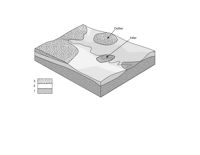
Sometimes the combination of topography and geology can produce map patterns that are quite complicated, with patches of one unit surrounded by others. An inlier is an exposure of older strata surrounded by younger, whereas an outlier is an exposure or erosional remnant of younger strata that are completely surrounded by older. These relationships are indicated in Figure 1, which represents an eroded succession of strata; unit 1 is the oldest and 3 is youngest.
Stratigraphic units
Formations
The primary unit of mapping in stratified rocks is the formation. One of the first jobs in mapping a new area is to define formations.
A formation must be:
- Mappable at whatever scale of mapping is commonly practised in a region;
- Defined by characteristics of lithology that allow it to be recognized;
- It must have a type section that exemplifies those characteristics;
- It must be named after a place or geographical feature.
Other rules for defining formations are contained in the North American Stratigraphic Code and the International stratigraphic code.
Other lithostratigraphic units
Formations may be organized into groups.
Smaller mappable units may sometimes be recognized within formations. These are known as members.
Formations, groups, and members are all lithostratigraphic units. This means that they are based on lithological characteristics alone; age is not part of the definition.
Thickness calculations
Measured sections, showing the thicknesses of strata in a column format, are used often in stratigraphy and sedimentology. When strata are well exposed, it’s possible to measure the thickness of each bed with a tape measure. However, it’s often necessary to measure diagonally across dipping strata, so apparent thicknesses must be corrected for the difference between the measured direction and the direction that’s perpendicular to strata (called the pole to bedding).
There are numerous trigonometric formulas to convert true thickness to apparent thickness for different combinations of dipping planes and plunging lines of section. However, all are variations on a single basic formula.
True thickness = Apparent thickness × cos(θ)
where θ is the angle between the line of section and the ‘ideal’ direction represented by the pole to stratification. This angle can easily be determined from a stereographic projection, which we will cover in the next section.
Unconformities
Unconformities are ancient surfaces of erosion and/or non-deposition that indicate a gap or hiatus in the stratigraphic record. An unconformity may be represented on a map by a different type of line from that used for other geological contacts; in a cross-section an unconformity is often shown by a wavy or crenulated line.
Subtle unconformities are very important in the analysis of sedimentary successions. A sequence is a package of strata bounded both above and below by unconformities. It may be that an unconformity is a sequence boundary, but that determination depends on finding another unconformity in the succession, either higher up or lower down stratigraphically.
Angular unconformities
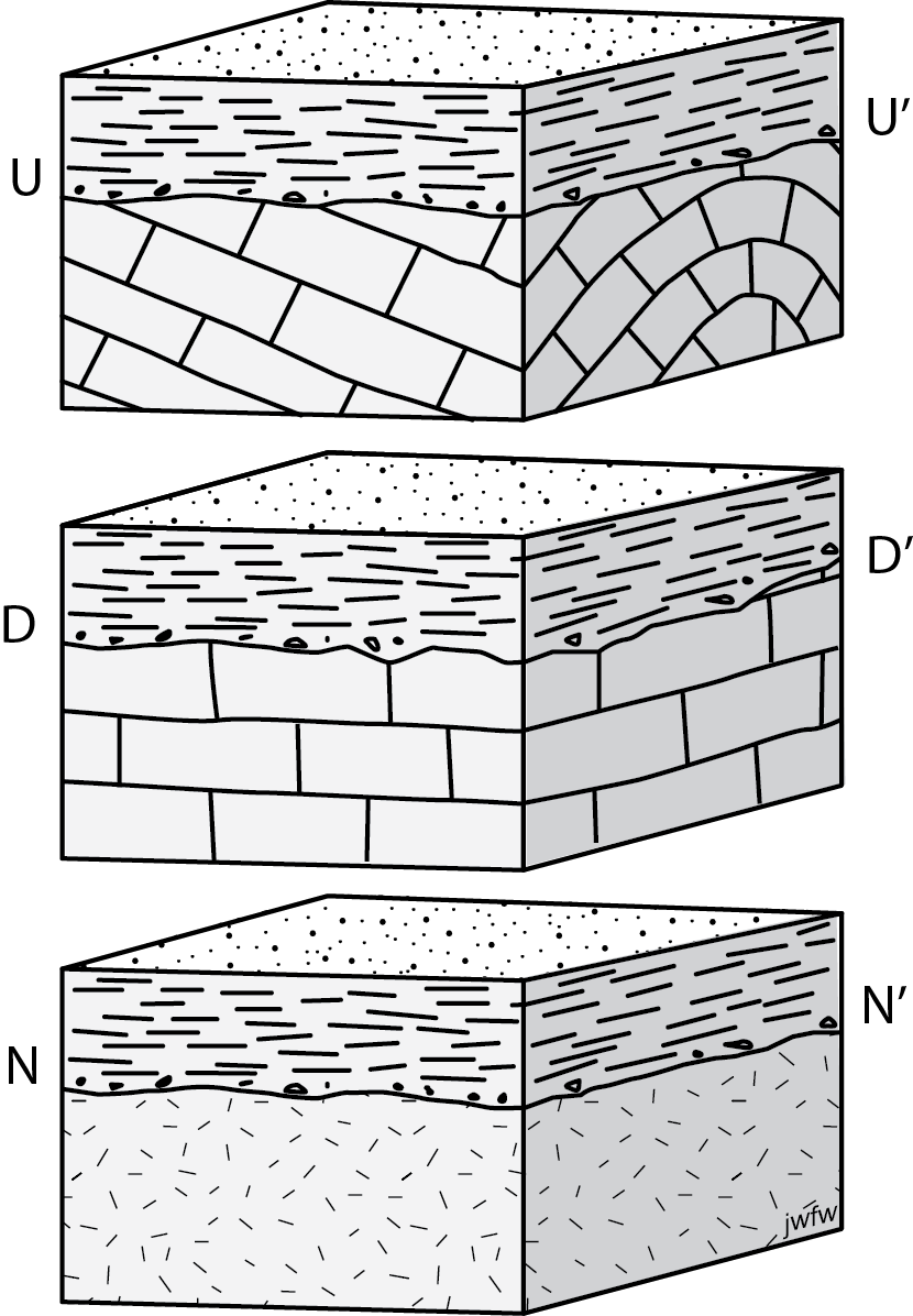
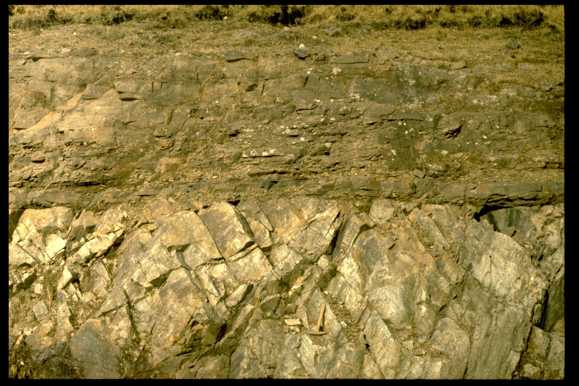
An angular unconformity is characterized by an angular discordance, a difference of strike or dip or both, between older strata below and younger strata above (Fig. 2a). In the diagram, the younger strata are horizontal. However, subsequent tilting of the entire succession could alter the orientations, but there will still be a discordance between strata above and below the unconformity. Bedding in the younger sequence tends to be parallel to the plane of unconformity, or nearly so.
Structure contours on the younger strata above the unconformity will not have the same orientation and spacing as those on the older strata below; either the strike or the dip, or both, will be different.
Disconformities
A disconformity is a contact between parallel strata whose ages are significantly separated (Fig. 2b). How can it be recognized? One may discern the erosion surface by observations of such features as stream channels, buried soil profiles, and pebbles/conglomerates. If the only evidence for a gap is from detailed paleontological investigation, the surface is a paraconformity. In either case, structure contours for strata both above and below the unconformity will be parallel and will have the same spacing.
Nonconformities
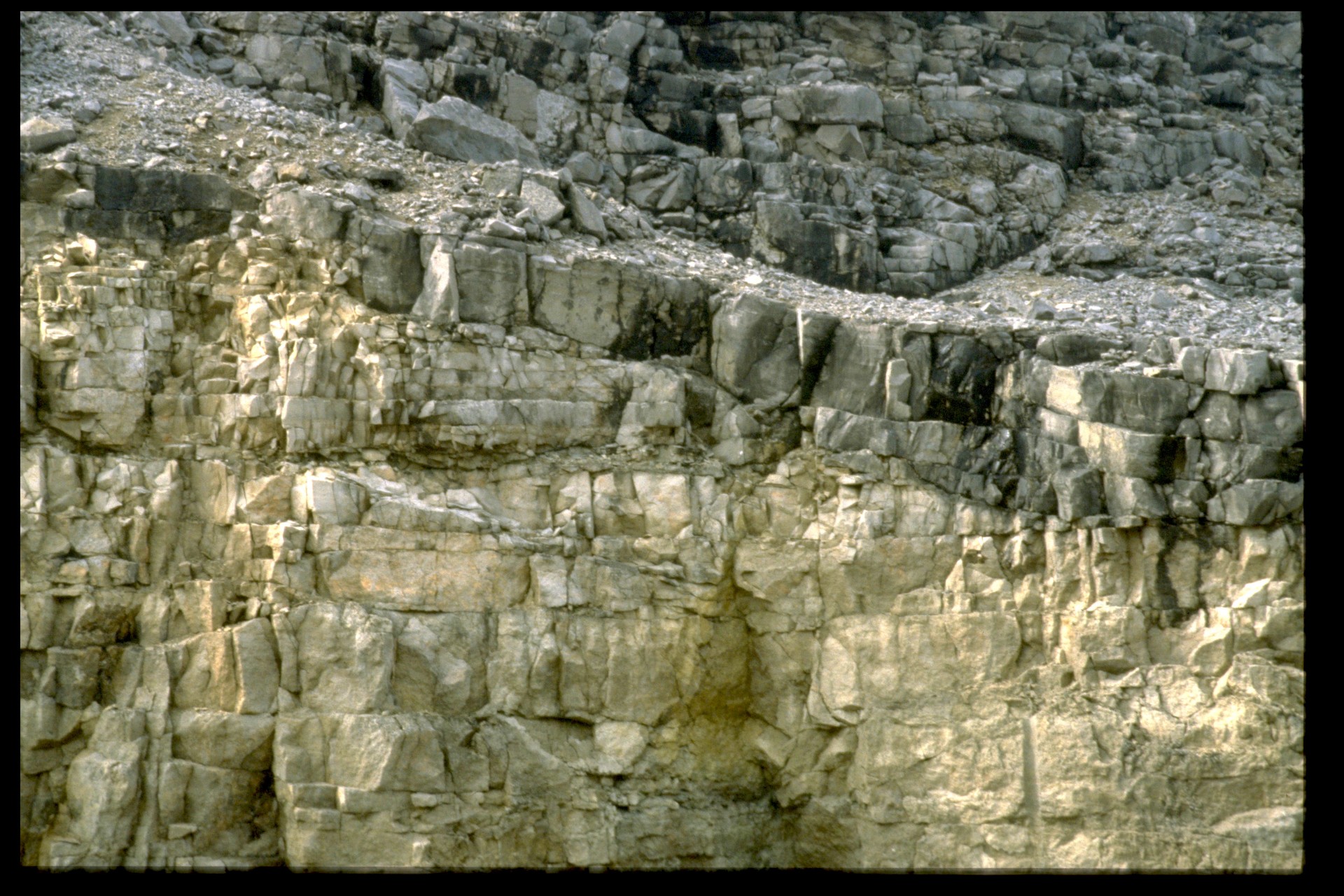
The term nonconformity is used to describe the contact between younger sedimentary strata deposited upon an eroded surface of older crystalline (igneous or metamorphic) rocks (Fig. 2c) in which distinct layers cannot easily be recognized. (In other words it is impossible to say whether the unconformity is angular or not.)
Be careful to distinguish a nonconformity from an intrusive contact. At a nonconformity, younger sedimentary rocks were deposited on an older intrusion. Typically there may be pebbles of weathered intrusive rock in the sedimentary rocks. At an intrusive contact, it is the intrusion which is younger. Surrounding older sedimentary rocks may show baking (thermal metamorphism), and the younger intrusion may contain pieces (xenoliths) of the older sedimentary rocks. Although an intrusive contact may be strongly discordant, it is not any kind of unconformity.
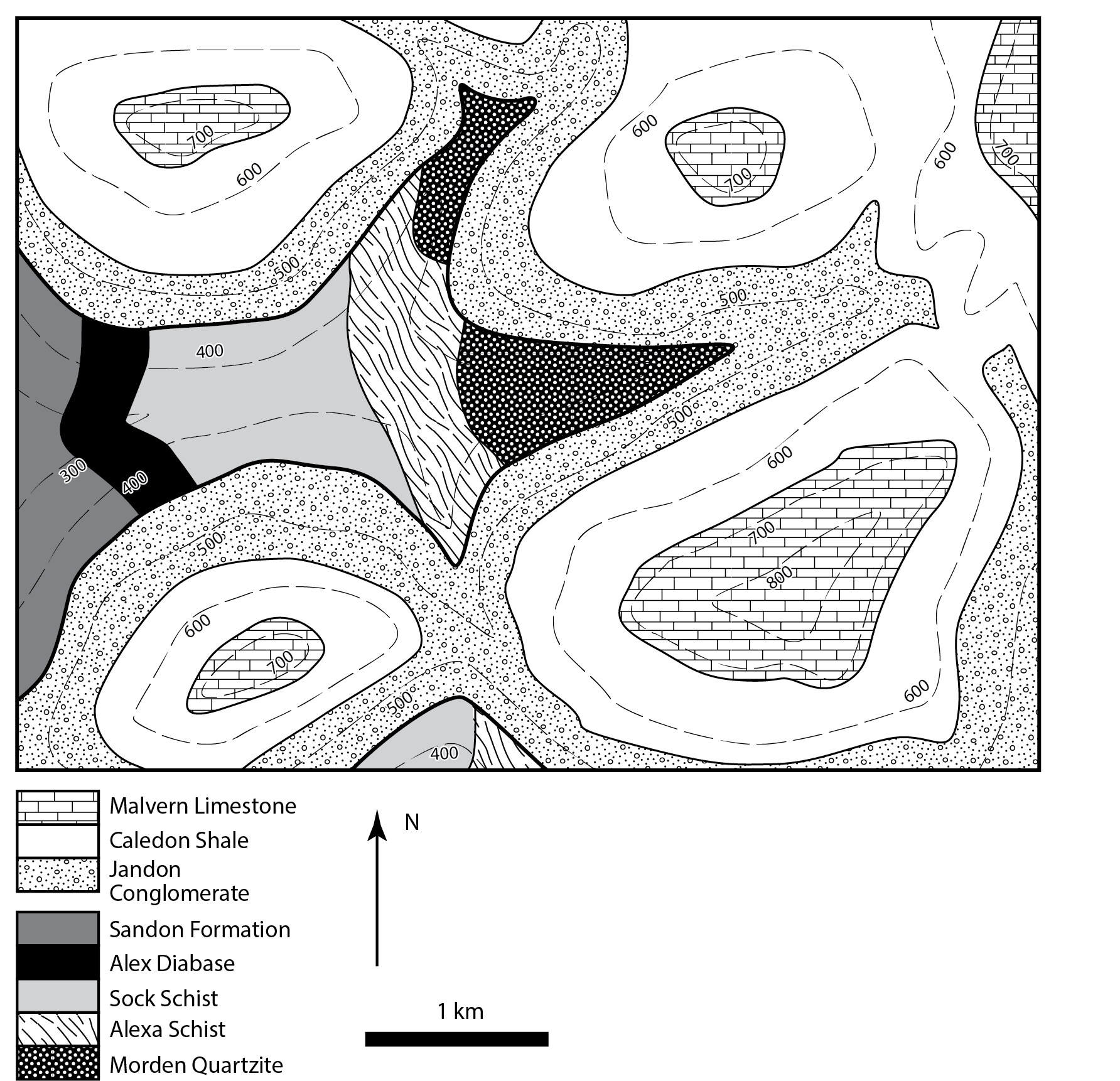
Unconformities in geologic maps
In many cases, angular unconformities can be recognized from geologic maps. The succession above the unconformity typically shows strata that are approximately parallel to the unconformity, whereas the rocks that underlie the unconformity are sharply cut off at the boundary.
Onlap and overstep
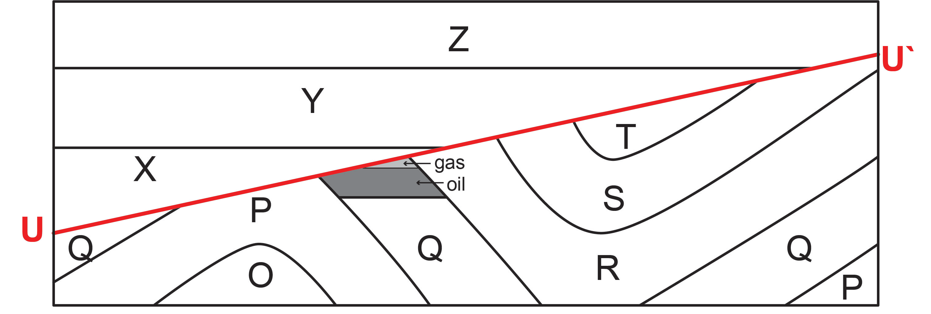
In a sedimentary succession containing an unconformity, the beds may show either onlap or overstep or both (Fig. 8). In that part of the succession above an unconformity, younger beds onlap the succession below if successively younger beds extend farther geographically onto the unconformity surface. The onlap relationship is generally produced by progressive burial of topography by a process called transgression (defined as landward movement of the shoreline). Overstep is a relationship involving strata below the unconformity, and describe the way the younger succession rests on a variety of units in the lower succession. In Figure 8, Y and Z onlap the unconformity, and Y oversteps from R onto S and T.
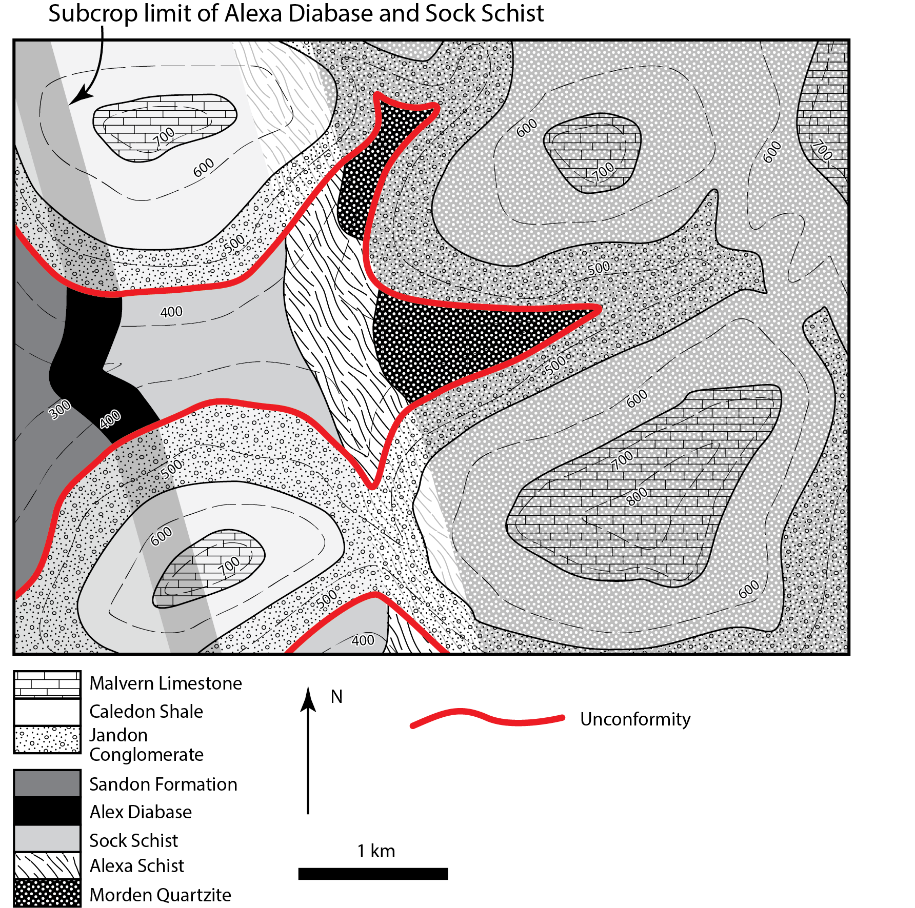
Paleogeologic maps and subcrops
If exposures of rock at the present-day erosion surface are referred to as outcrops, then rocks that were exposed at ancient erosion surfaces that are now buried are referred to as subcrops. Buried surfaces of erosion are unconformities, so subcrops represent those rocks directly below an unconformity. If we strip away all the rocks above an unconformity, we can produce a map of the subcropping units, which would be a paleogeologic map. In effect, it is a map of the geology as a prehistoric geologist would have recorded it just before renewed deposition began to bury the ancient erosion surface. In the cross-section of Figure 8, a paleogeologic map showing the distribution of rocks prior to deposition of units X-Z would show the eroded exposure of the folded succession P-T. In Figure 9, the subcropping units are shown “greyed out” below the unconformably overlying succession.
The intersection of a plane representing the erosion surface and a geological surface below the unconformity is the subcrop limit of that older surface. It can easily be determined by finding the intersections between corresponding structure contours on the unconformity and the older surface. The subcrop limit is the boundary between a region where the older surface is preserved below the unconformity, and a region where it was eroded. In the first region, the unconformity structure contours are higher than the older surface; in the second, the structure contours on the unconformity show it is lower.
In practical terms, there are many hydrocarbon traps at subcrop limits of reservoir rocks below angular unconformities in the Western Canada Sedimentary Basin. Lighter oil and gas migrate in the up-dip direction through buried reservoirs, until they encounter impermeable younger rocks above an unconformity. The search for such an occurrence is called a subcrop play in the petroleum industry.
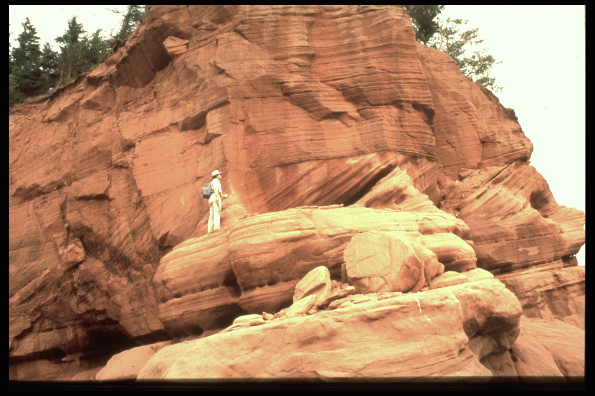
Primary structures in sedimentary rocks
Stratification
Outcrop-scale: bedding, lamination
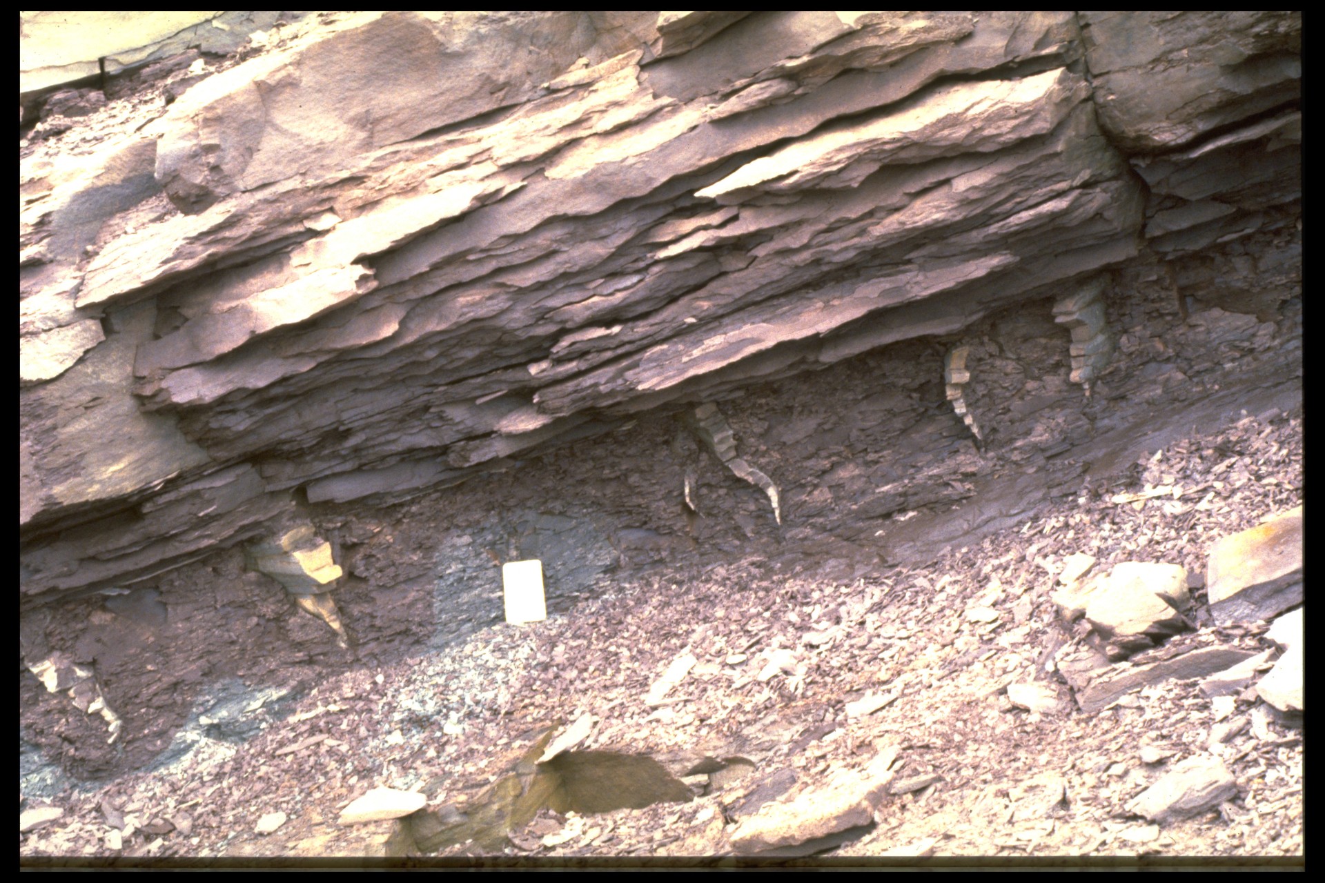
Strata are often seen at outcrop scale too, and are one of the main characteristics that allow us to recognize sedimentary rocks.
Layers thicker than 1 cm are known as beds. A layer thinner than this is a lamina (plural laminae).
Several sedimentary processes (storms, turbidity currents) suspend large amounts of sediment in a sudden event, and allow it to settle out slowly, producing a graded bed with a sharp base, above which the grain-size progressively fines upward. Graded beds are useful indicators of younging direction: i.e. in highly deformed rocks, they indicate whether or not the strata are overturned. However, graded beds must be used with caution because there are sedimentary processes that can produce inverse grading. For example, densely moving masses of colliding grains, avalanching down a steep slope, tend to interact so that the large grains rise to the top. Therefore graded bedding should only be used as a way-up indicator if it is seen multiple times in a succession of strata.
Structures generated by currents, way-up indicators
We have already mentioned graded bedding as an indicator of way-up, or younging direction. Many other sedimentary structures can be used as way-up indicators.
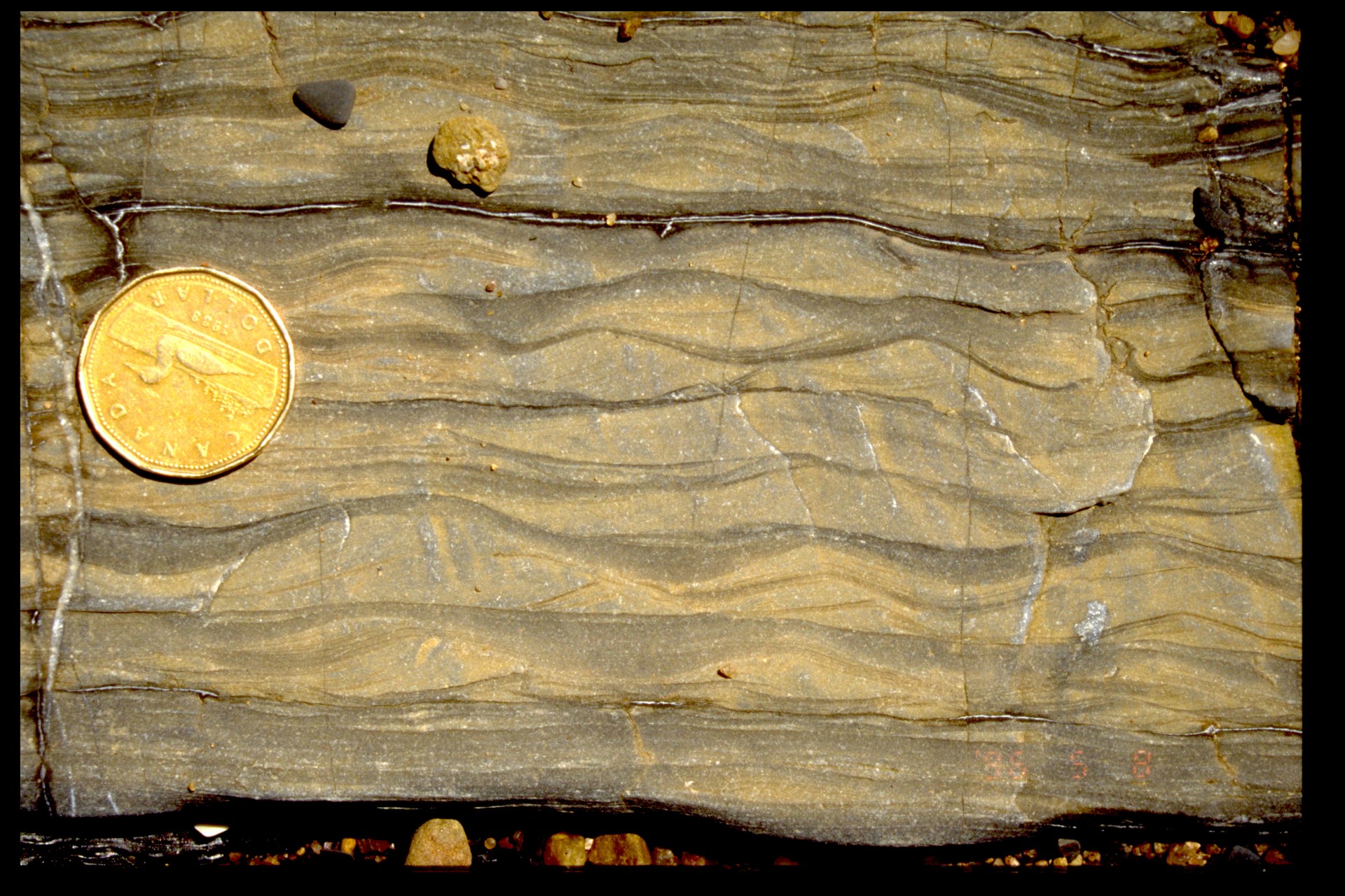
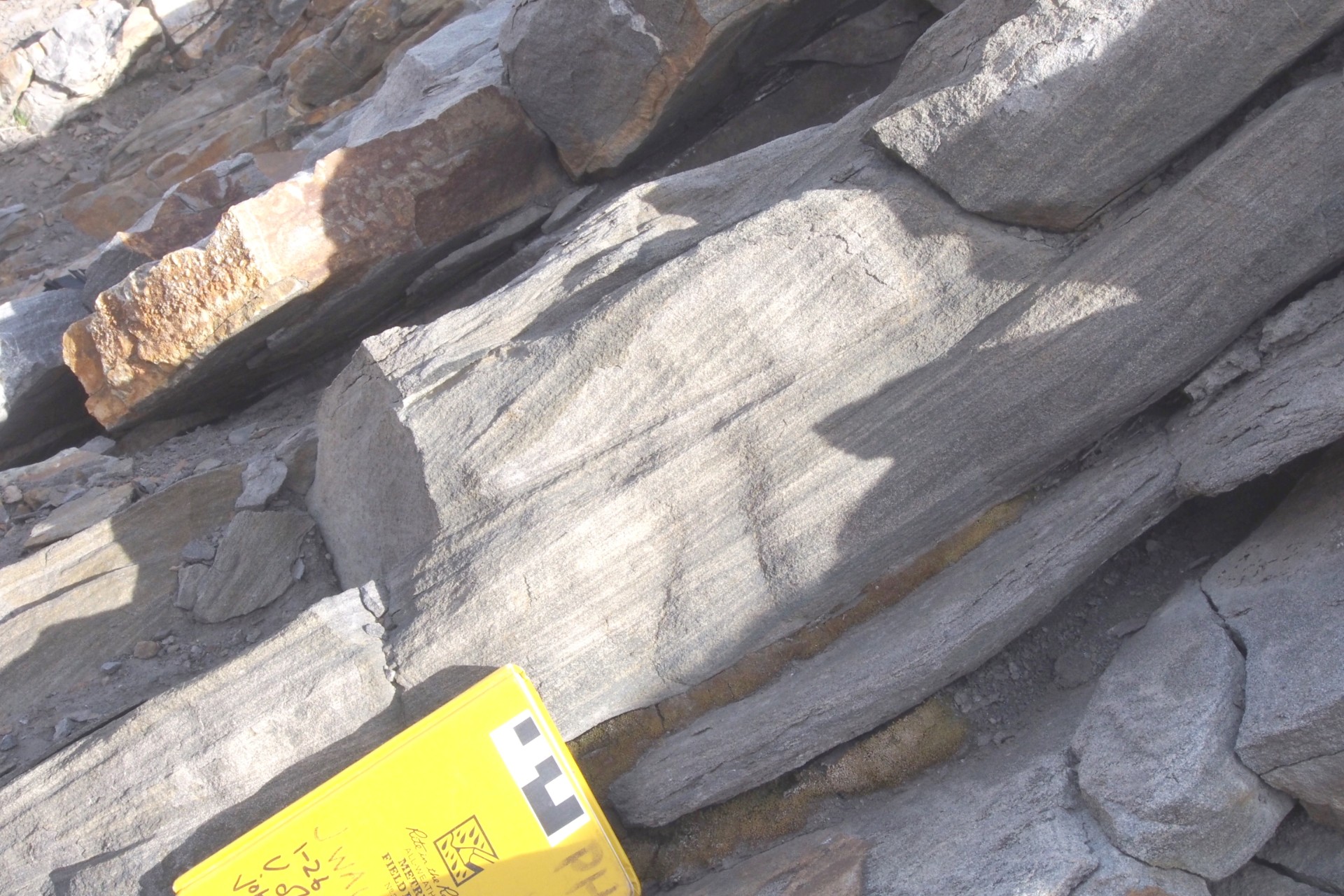
Bedforms and cross-stratification
Amongst the most useful is cross-stratification. Cross-stratification results from the migration of bedforms during sedimentation. Bedforms are waves on the bedding surface produced by the action of either currents or waves.
Bedforms are generally classified into larger forms, called dunes, and smaller types called ripples. By convention:
- cross-stratification produced by dunes is called cross-bedding;
- cross-stratification produced by ripples is called cross-lamination.
Cross-stratification indicates way-up most effectively because it produces truncations of laminae, that resemble small-scale angular unconformities. The laminae that are truncated are always below the truncation surface.
Even if truncations cannot be seen, it’s sometimes possible to use cross lamination by noting that most bedforms have ridges that are sharper – more pointed – than the troughs. However, in deformed rocks it’s sometimes the case that the curvature of surfaces is modified. Truncations therefore give a more certain indication of way-up than lamination shape.
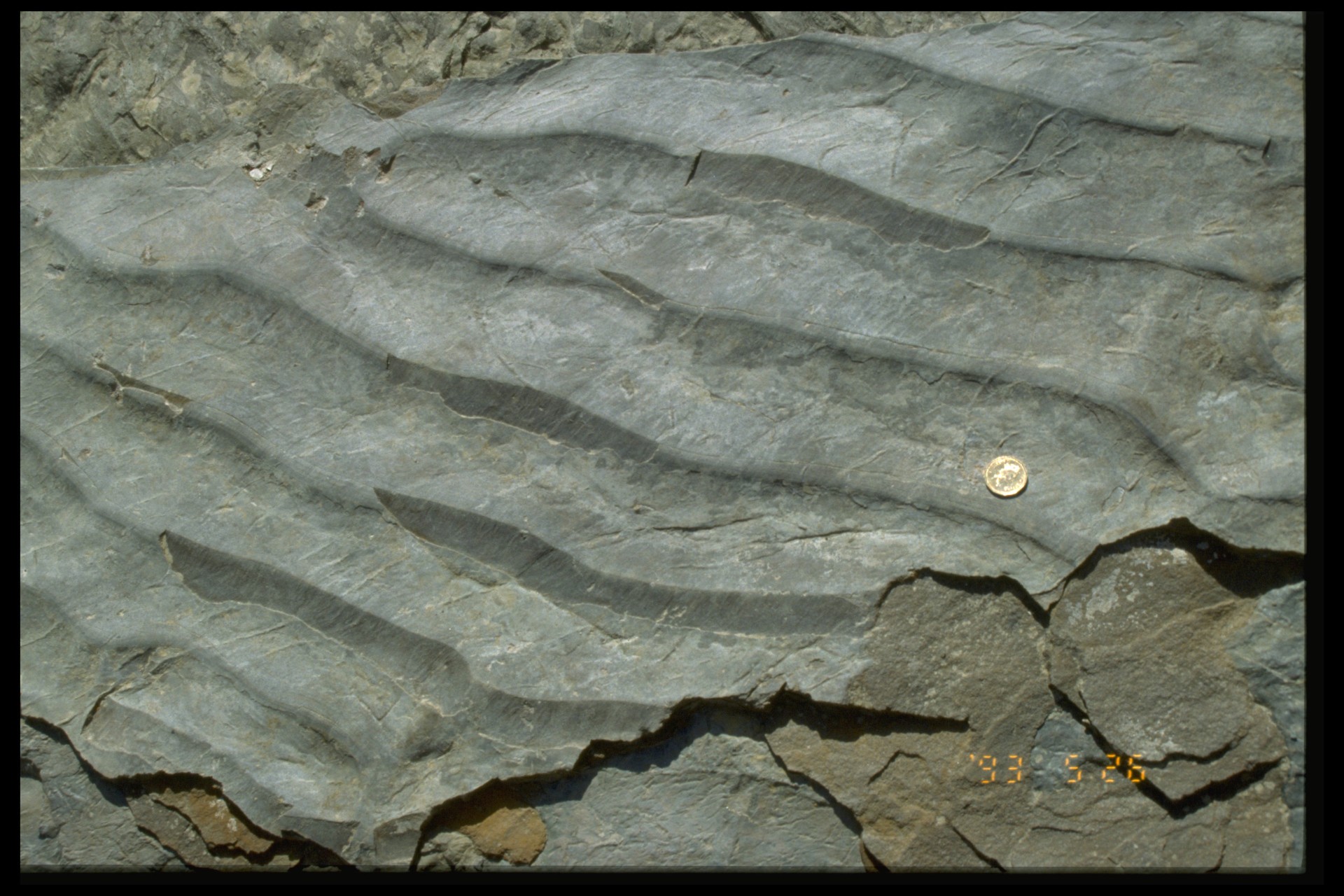
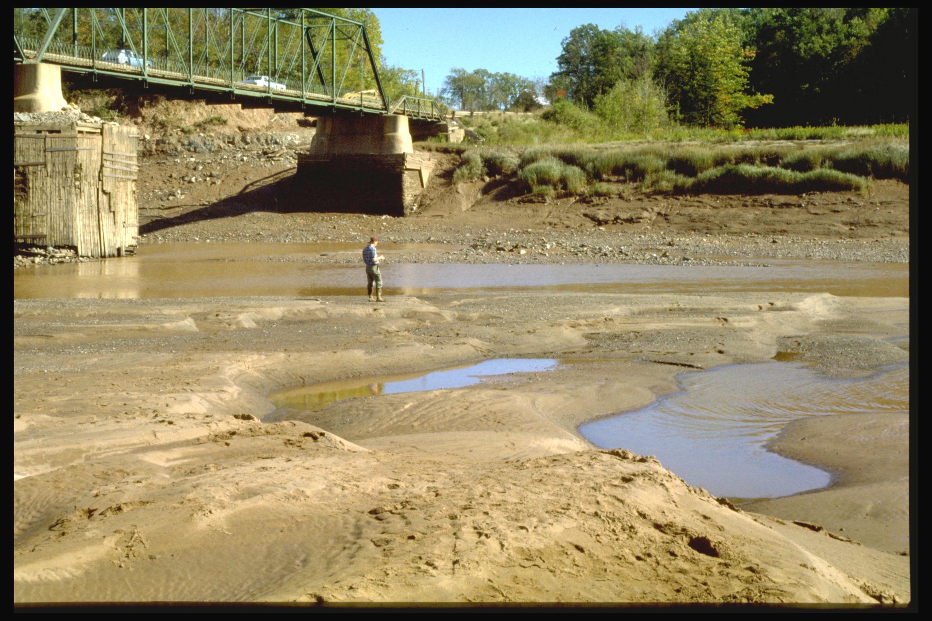
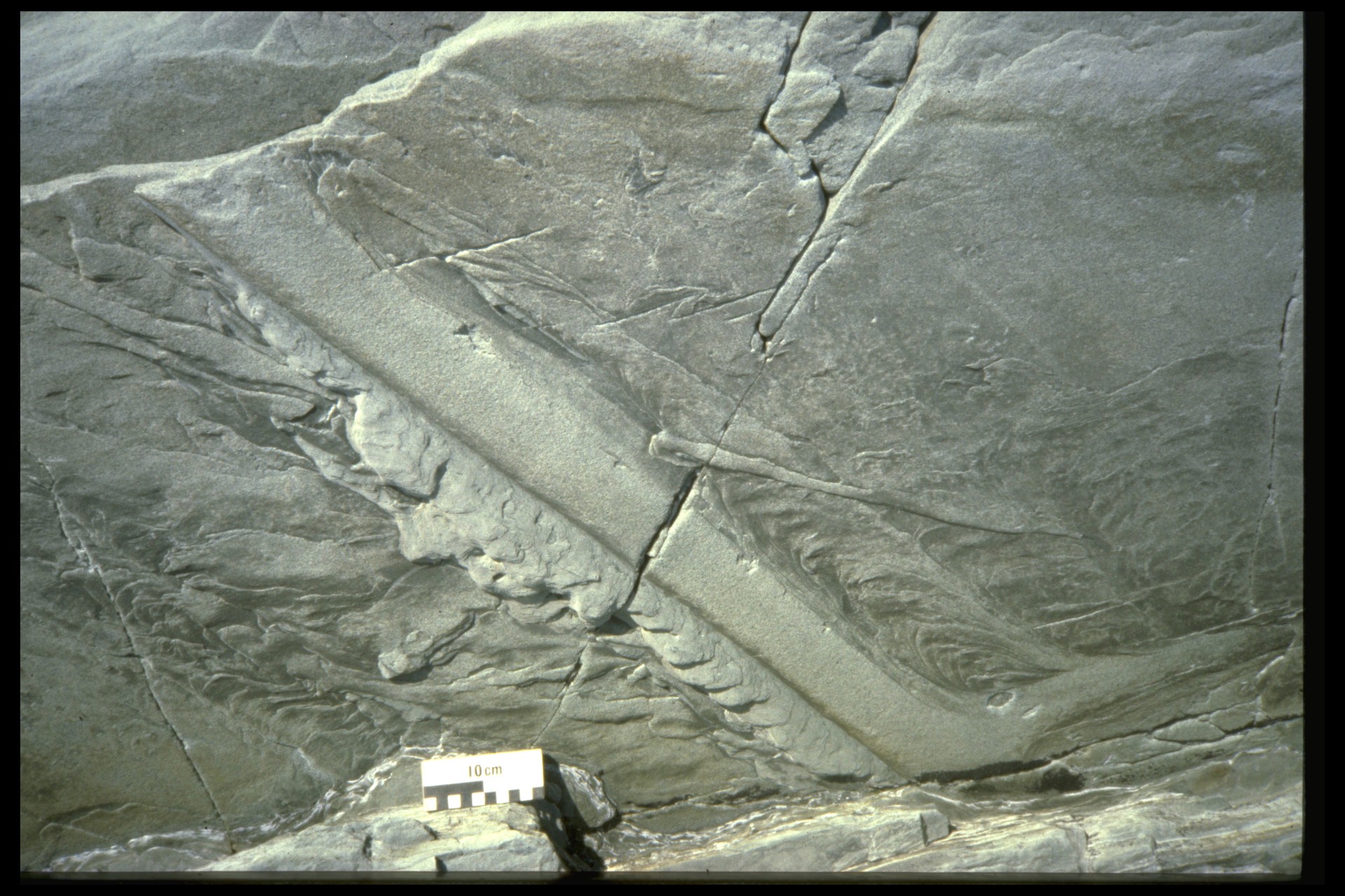
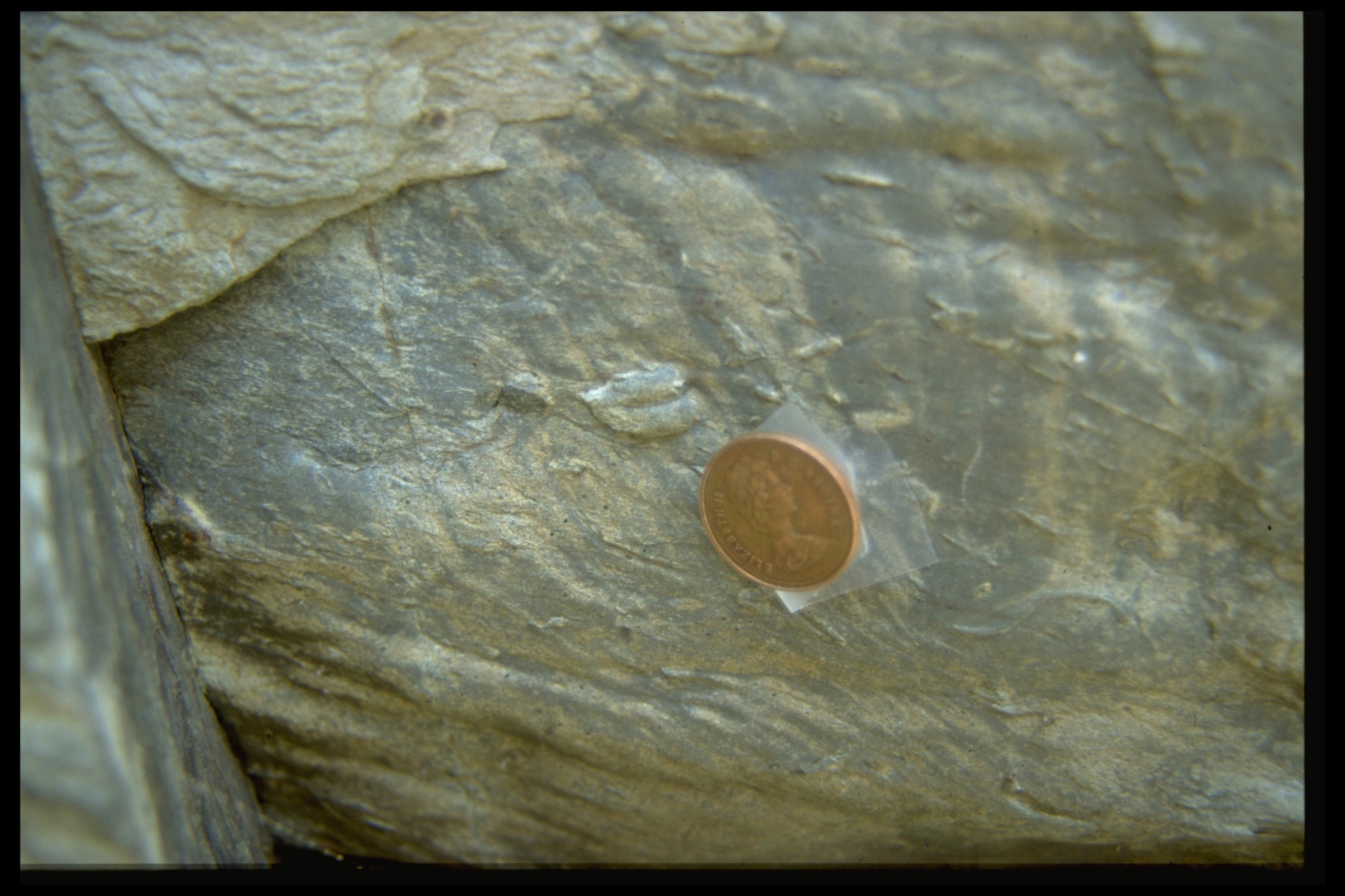
Sole markings
Sole markings are a second type of sedimentary structure that is useful for structural geologists. Sole markings are formed when coarse sediment (usually sand) is deposited rapidly (usually by a current) on a muddy substrate. Sole markings include:
- Groove casts: grooves are made by currents dragging objects across the mud; these are then filled by sand and preserved as molds on the base of a sandstone bed;
- Flute casts: currents produce scoop-like depressions in the mud that fade out in a down-current direction; these are then filled by sand and preserved as molds on the base of a sandstone bed;
- Bioturbation structures (trace fossils): horizontal burrows and trails are filled by sand and preserved as molds on the base of a sandstone bed.
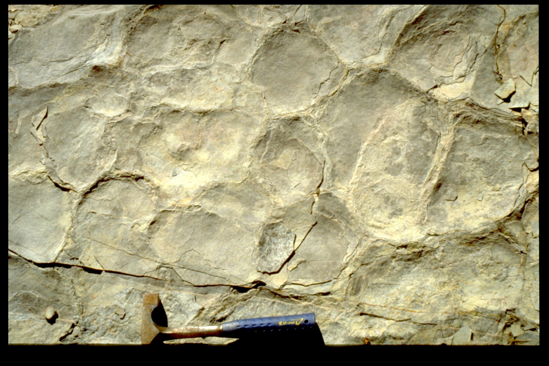
- Load structures: bulges in the bottom of a sandstone bed formed when denser sand sinks into less dense wet mud.
Note: strictly speaking, all these structures should be called molds, not casts. However, the term ‘cast’ is more commonly used.
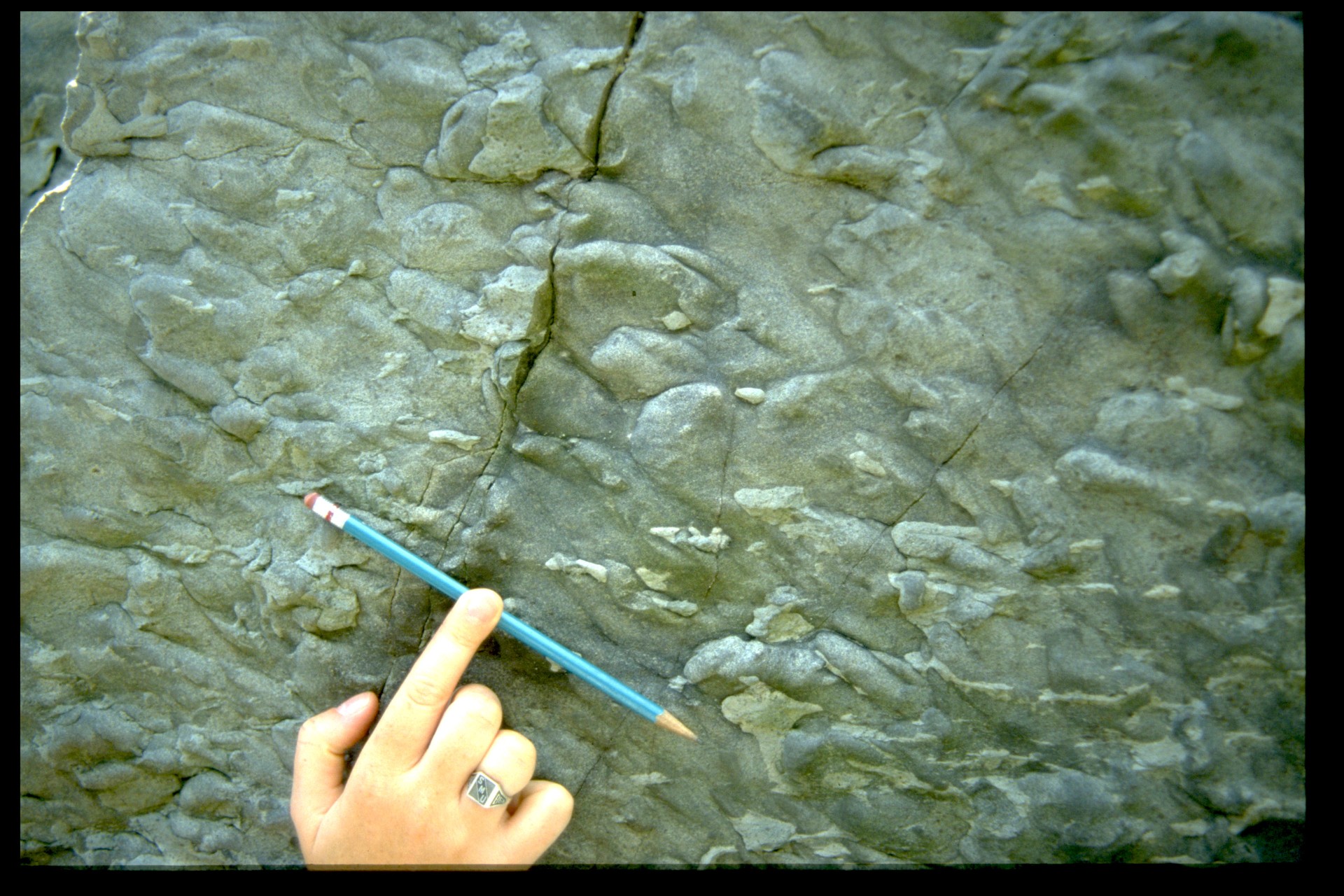
Structures generated by soft-sediment deformation
Recently deposited sediment may be deformed while it is unlithified. Soft-sediment deformation structures can be challenging for the structural geologist as they are difficult to distinguish from tectonic structures, formed after the sediment was lithified. There are a number of categories.
- Mudcracks: these are formed by shrinkage of mud as it dries out. Mudcracks are most visible when they are filled by overlying sediment that is different. They thin downwards to a point and therefore can be good way-up indicators.
- Load structures: bulges in the bottom of a sandstone bed formed when denser sand sinks into less dense wet mud. Load structures also fall into the category of sole markings. Corresponding narrow tongues of mud penetrating upward between load structures are called flame structures.
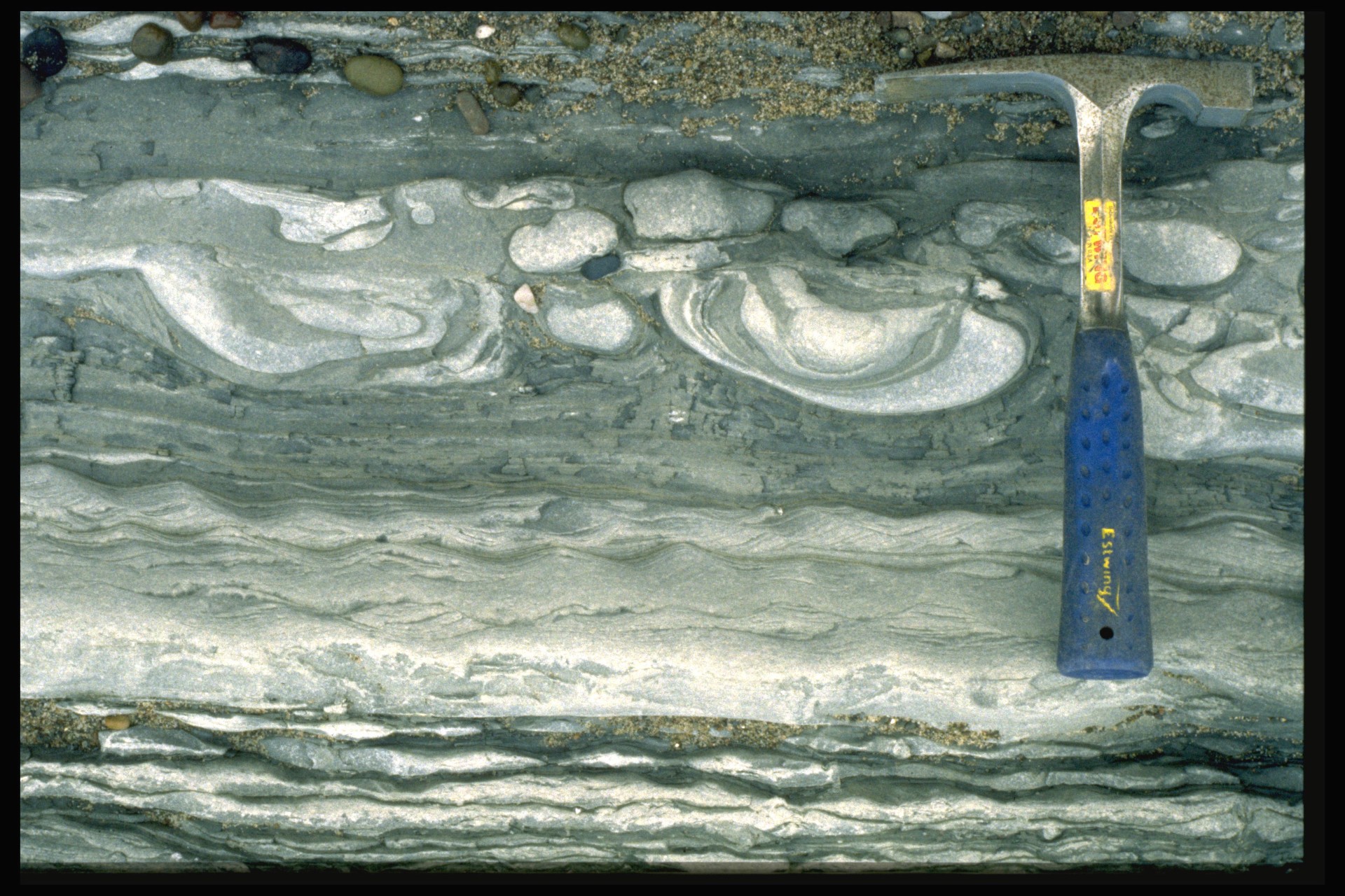
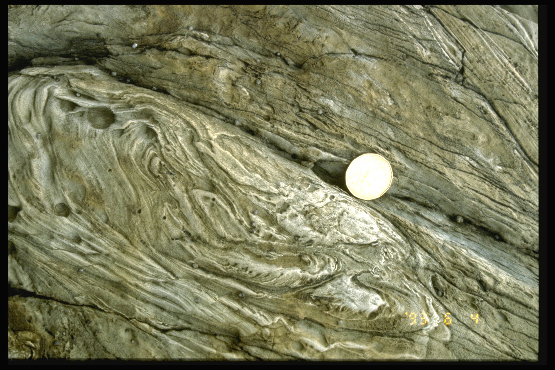
- Convolute lamination: sand that is deposited under water is often initially very loosely packed. Subsequently, the grains may settle into a denser packing, and the water between the grains escapes upward. As this occurs, the water may liquidize the sand. Any lamination may become deformed into complex chaotic folds. Convolute lamination is only a good way-up indicator if it is truncated by younger laminae.
- Slump structures: sediments that are deposited on a slope may undergo catastrophic slope failure, and start to move under the influence of gravity. Beds may become tightly folded as a result of this type of process. Slump folds can be difficult to distinguish from tectonic folds, and are not particularly effective as way-up indicators. However, if the way-up is known from other structures, slump folds can be used in sedimentology and basin analysis as indicators of paleoslope.

Primary structures in igneous rocks
Intrusions
Intrusions by their nature do not typically show stratification, and cannot usually be used to determine tilting or way-up. However, in unravelling the structural history of a complex region, it is important to know the relative timing of intrusions, and this is where contact relationships are all-important.
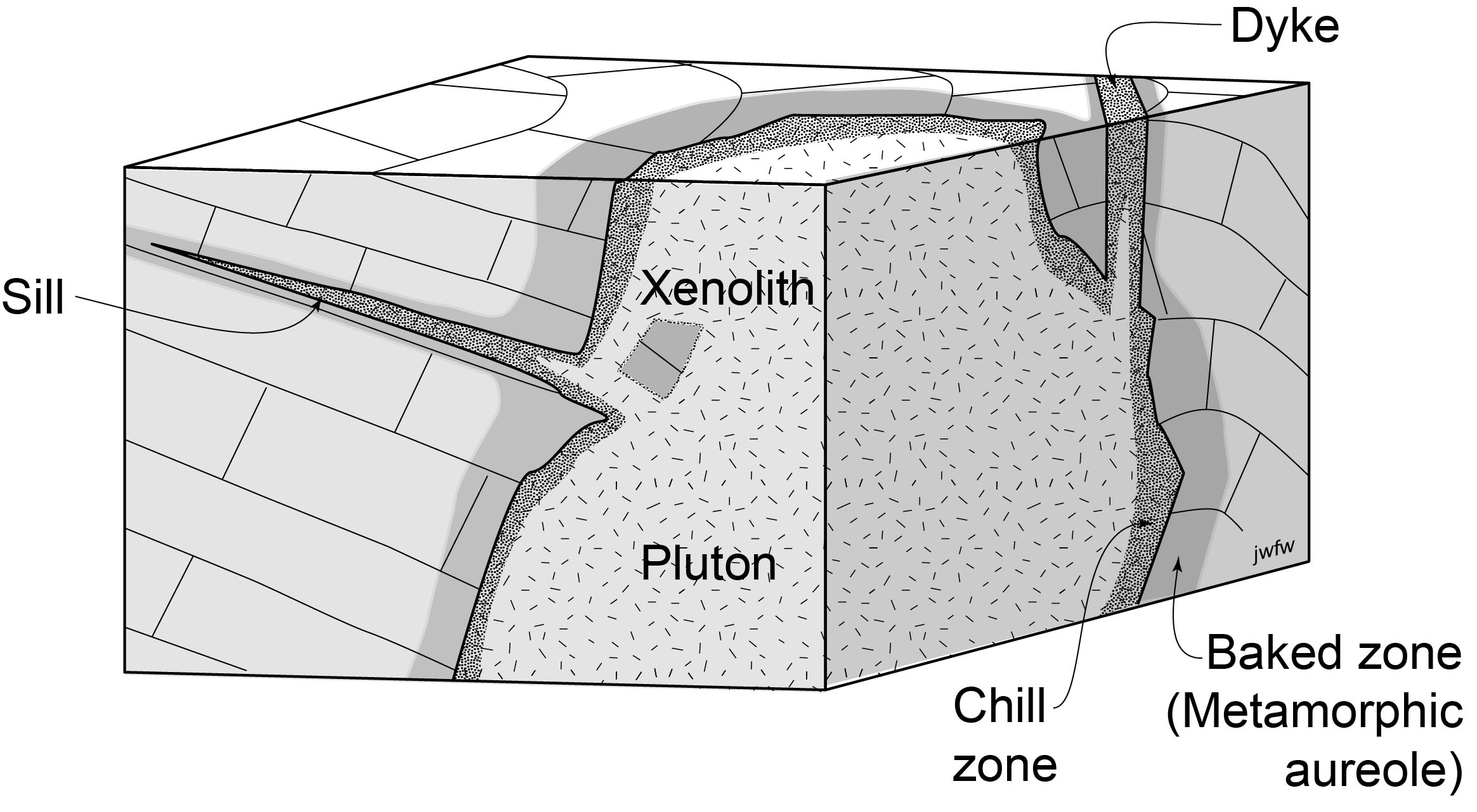
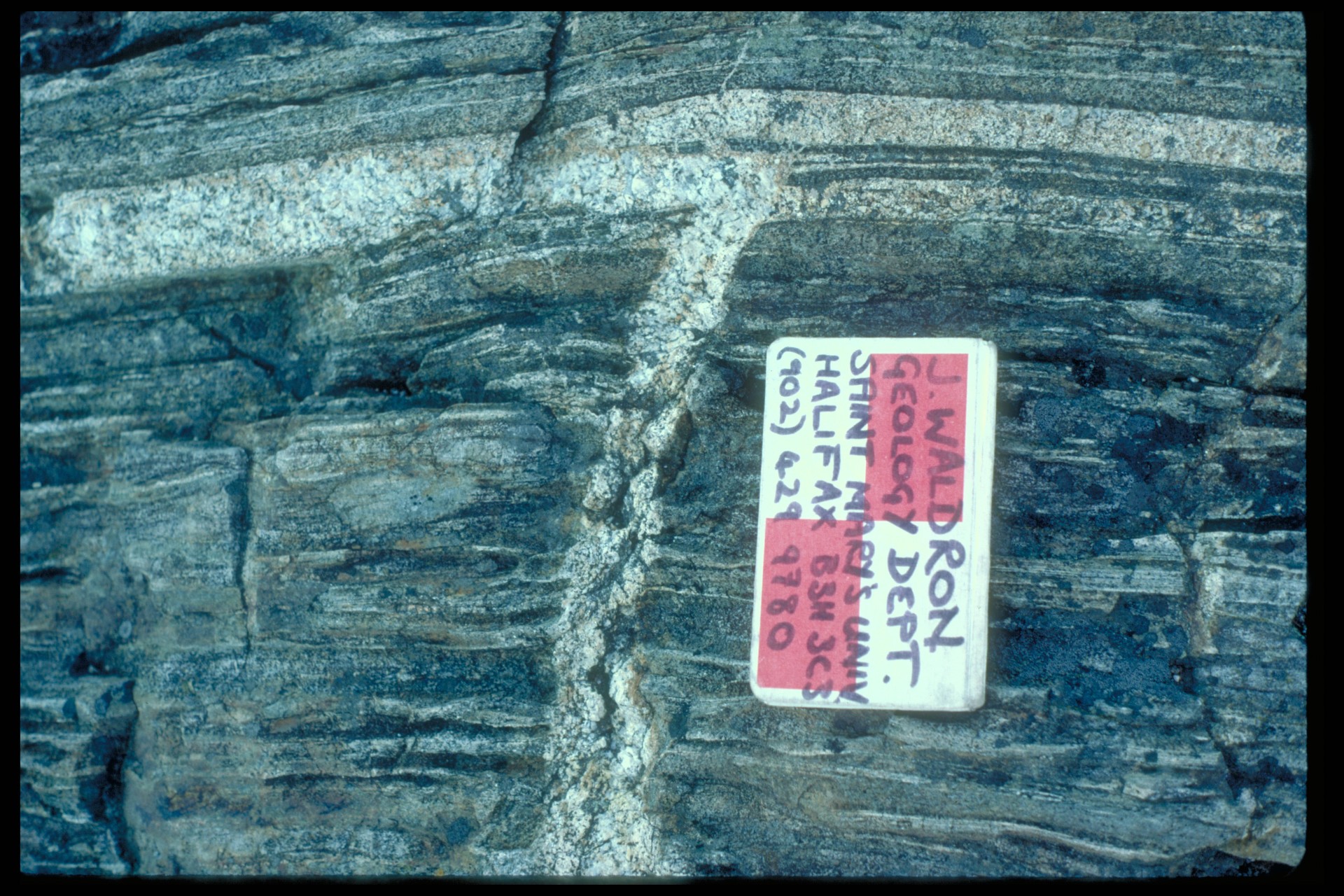
Exocontact features are formed in the host rock (also known as country rock) by the effect of an intrusion. A metamorphic aureole (baked zone) is often recognizable from changes in texture or mineralogy. There may be minor intrusions where magma has filled cracks branching off the main intrusion. These are called dykes (dikes in the US) unless they are parallel to strata in the host rock, in which case they are sills.
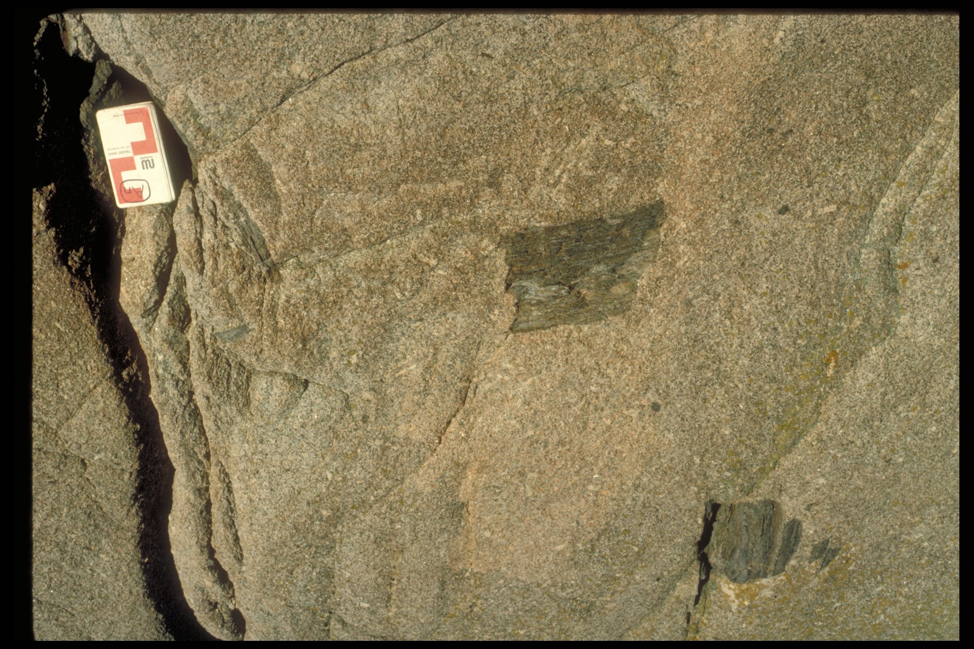
Endocontact features are formed within an intrusion, where it comes in contact with the host rock. A chill zone is typically finer-grained than the bulk of the intrusion. Xenoliths are pieces of host rock that broke off and are surrounded by the intrusion.
Volcanic rocks
Volcanic rocks are typically stratified, but bedding is often much less clear than in sedimentary rocks. Sometimes the contacts between volcanic flows are conspicuous because they are weathered. Soil layers called ‘bole’, consisting of soft, clay-rich weathered lava are sometimes visible.
Lava erupted under water typically forms balloon-like pillows typically 0.5 – 2 m in diameter, formed by rapid chilling. Later pillows conform in shape to those beneath them in a flow, giving a general indication of way-up.
Thick lava flows may shrink and crack as they cool, producing columnar joints. These typically form perpendicular to the base and top of a flow. As a result, the columns are elongated in the direction of the pole to stratification and therefore can be used to estimate the orientation of strata where bedding cannot be observed directly.
Note that columnar joints are common in sills too. Sills can be distinguished from flows only by looking at their contacts: sills show intrusive contacts top and bottom, whereas flows typically show one weathered surface.

A geologic structure formed at the same time as the rock in whichit is found.
Organised in layer (strata) that were originally horizontal.
The primary unit of mapping in stratified rock; must be mappable, defined by lithological characteristics, have a type section, and be named for a place or geographical feature.
A lithostratigraphic unit consisting of several formations.
A smaller mappable unit recognized within a formation.
The study of the organization and history of stratified rocks.
The principle that most stratified rocks were deposited in layers approximately parallel to the Earth's surface.
The principle that stratified rocks form with the oldest layers at the bottom, and youngest at the top.
A region on a geologuc map where older strata are surrounded by younger strata.
A region on a geologic map where younger strata are completely surrounded by older strata.
A named rock layer recognized on the base of its lithological characteristics.
An ancient surface of erosion and/or non-deposition that indicates a gap in the stratigraphic record.
A package of strata bounded above and below by unconformities.
An unconformity characterised by an angular discordance (a difference of strike or dip or both) between older strata below and younger strata above.
A difference of orientation between planes: difference of strike or dip or both.
An unconformity between strata of different ages but identical orientation.
A disconformity where the only evidence for a time-gap is from detailed paleontological investigation.
An unconformity formed by the contact between younger sedimentary strata deposited upon an eroded surface of older crystalline rock.
The relationship of successively younger beds that extend farther geographically onto an unconformity surface, generally produced by progressive burial of topography during transgression.
A relationship involving strata below an unconformity, that describes the way the younger succession rests on a variety of units in the lower succession.
A region of exposed rock at the present-day erosion surface.
A feature on an unconformity surface formed where the unconformity cuts off (intersects) a older rock unit or surface.
A map of subcrop units below and unconformity; the geologic map that would be produced if all rocks above an unconformity were stripped away.
A line on an angular unconformity surface making the boundary of an older unit that was partially removed by erosion at the unconformity surface.
Sedimentary layers thicker than 1 cm.
A layer thinner than 1 cm; plural "laminae".
A bed, usually with a sharp base, in which grain-size becomes finer toward the top.
Grain-size variation within a bed in which coarser grains are concentrated at the top.
A configuration of laminae produced by migration of bedforms during sedimentation, in which laminae are oriented at an angle to the depositional horizontal.
Cross stratification caused by dunes.
Cross stratification produced by ripples.
Sedimentary structures, such as flute and groove casts, preserved when coarse sediment is deposited rapidly on a muddy substrate.
A sedimentary structure formed when a groove is filled by sand and preserved as a mold on the base a bed.
A sedimentary structure formed when a flute is filled by sand and preserved in relief on the base of a sandstone bed.
Structures produced by organisms that have disturbed sediment.
A soft-sediment deformation structure caracterized by rounded bulges, typically on the base of a sandstone bed.
Thin fractures on the surface of beds that thin downward, form by shrinkage of mud as it dries.
A narrow, pointed soft-sediment deformation structure consisting of mud forced up into overlying sand.
A soft-sediment deformation structure in which laminae are deformed into complex chaotic folds.
A process whereby previously deposited sediment behaves as a liquid, when the sand grains become separated by fluid
A soft sediment structure formed in sediments deposited on a slope that undergo catastrophic slope failure, and move under the influence of gravity. Beds may be tightly folded, boudinaged, or both.
The region in the host rock (country rock) affected by contact with an intrusion.
A minor intrusion where magma has filled a crack that is discordant to layers in the surrounding rocks. (Spelled 'Dike' in the U.S.A.)
Dyke (U.S. spelling)
A tabular igneous intrusion where magma has intruded parallel to strata in the host rock.
Typically finer-grained material found near the edge of an igneous intrusion, typically formed by rapid coolling
A piece of host rock that is surrounded by an intrusion.
Balloon-like structures formed by rapid chilling of lava erupted under water.
Joints that separate elongated bodies of rock that are typically polygonal (roughly hexagonal) in cross-section. These typically form perpendicular to the base and top of an igneous flow or sill.
